
Assembly and setup
Contents overview
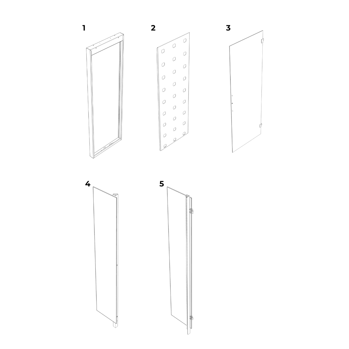
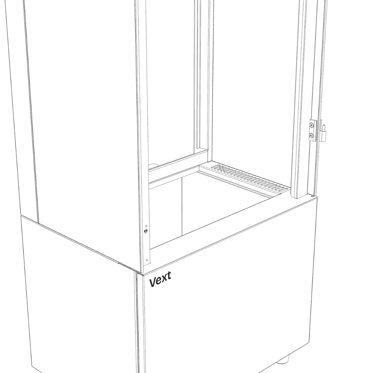
Box A
1. Frame
2. Plant wall
3. Glass door
4. Left-glass module
5. Right-glass module
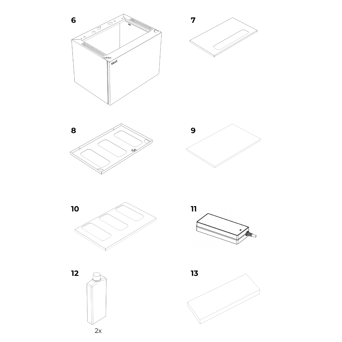
Box B
6. Base
7. Water tank lid
8. Top panel
9. Top filter
10. Filter cover
11. Power adapter
12. Nutrient bottles (x2)
13. Starter plant pack
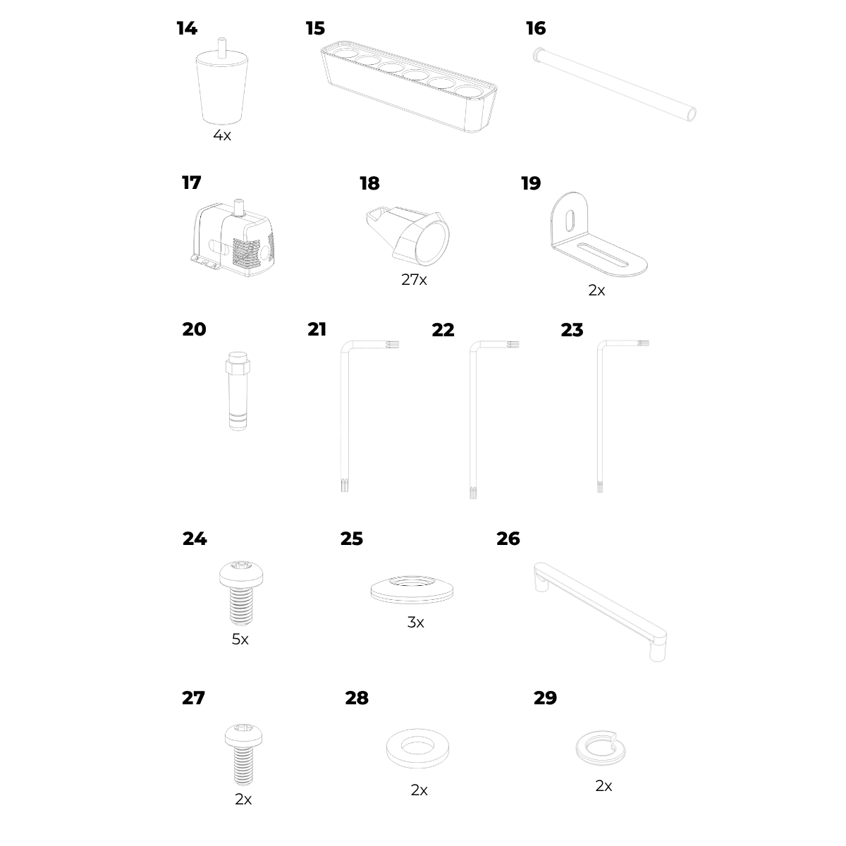
Accessory box (Inside Box B)
14. Feet x4
15. Plant starter
16. Drain tube
17. Water pump
18. Pod holders x27
Mounting hardware:
19. Mounting brackets x2
20. Antenna
Fasteners and tools:
21. Torx key (T25)
22. Torx key (T20)
23. Torx key (T10)
24. Screws (M5) x5
25. Sealing washers x3
Door handle assembly:
26. Door handle
27. Screws (M4) x2
28. Washers x2
29. Spring washers x2
Assembly steps
Before you begin assembly, choose a suitable location for your cabinet, ensuring access to power and Wi-Fi.
WARNING – Electric shock risk
Do not connect power during assembly.
CAUTION – Handling and stability
Two persons required.
Handle the tempered glass panels carefully and avoid impact on corners.
Once assembled, do not lift or move the cabinet.
NOTICE – Assembly care
During assembly, place parts on a surface that will not scratch or damage them.
Align each connector before inserting. Push straight in without forcing. Insert until fully seated.
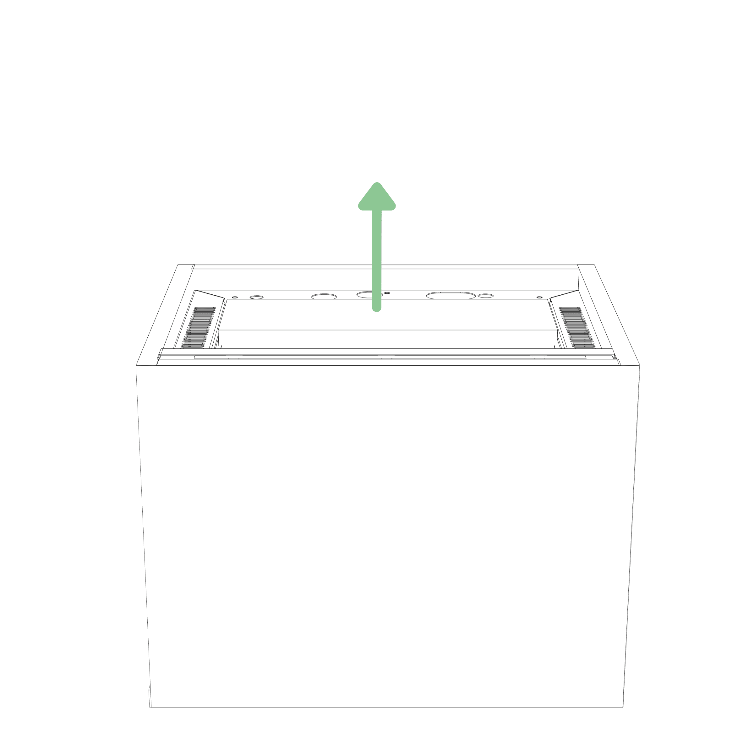
Step 1
Remove the accessory box from inside the water tank and unpack all contents.
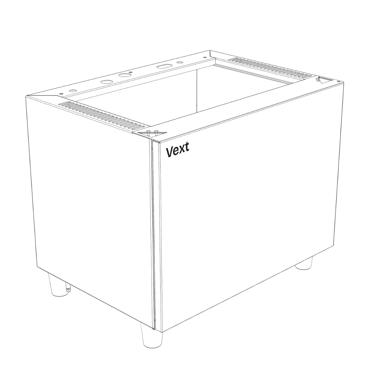
Step 2
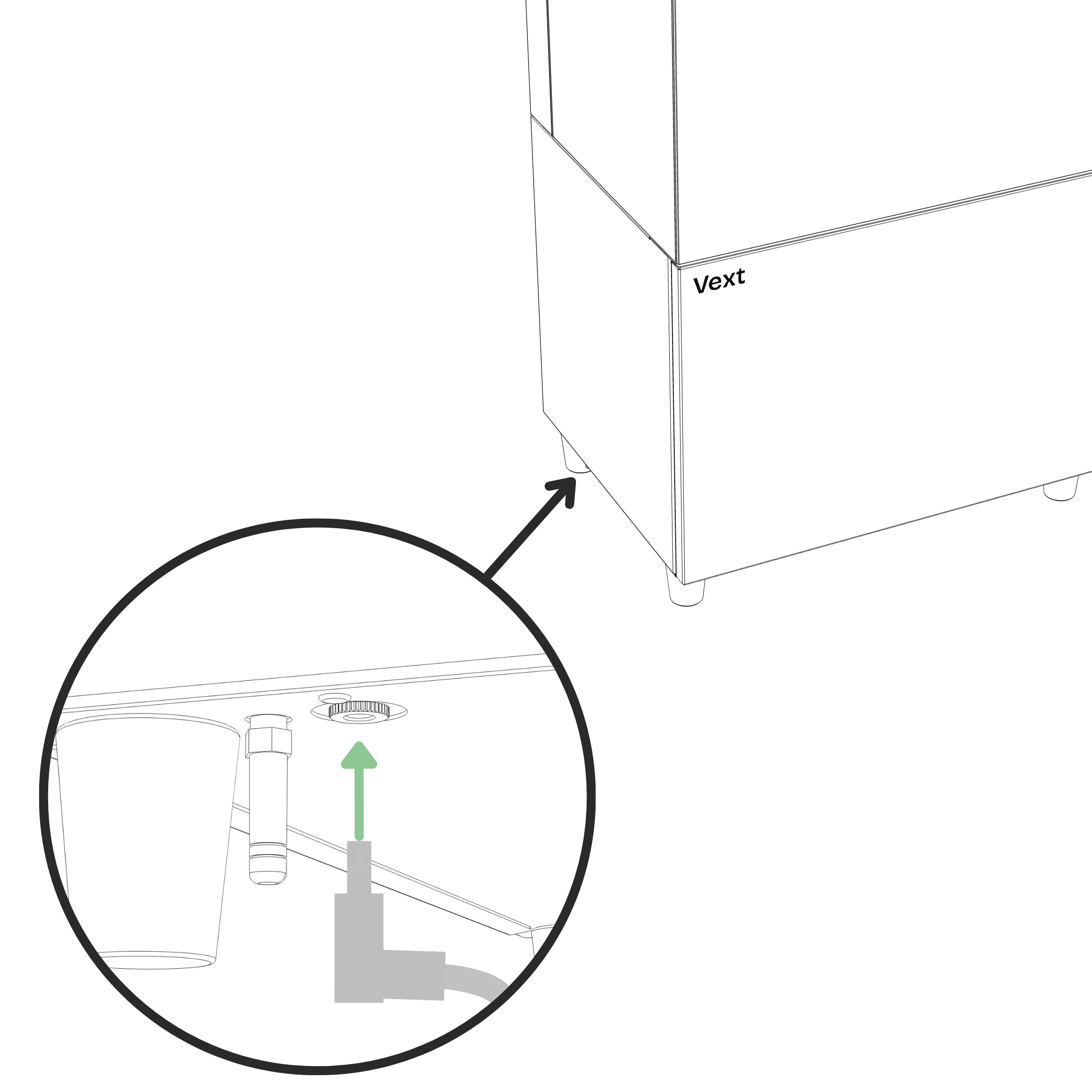
Screw the feet into the bottom of the base until hand-tight.
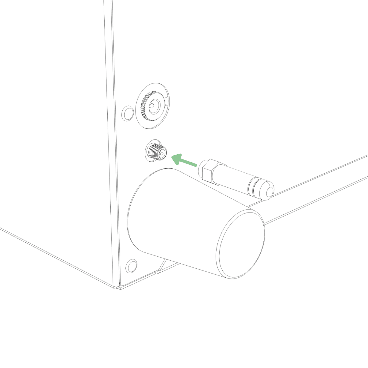
Step 3
Hold the metal nut at the base of the antenna and screw it onto the threaded connector on the bottom of the base until hand-tight.
Step 4
Remove the protective plastic from the bottom of the base, then place the base in its final location.
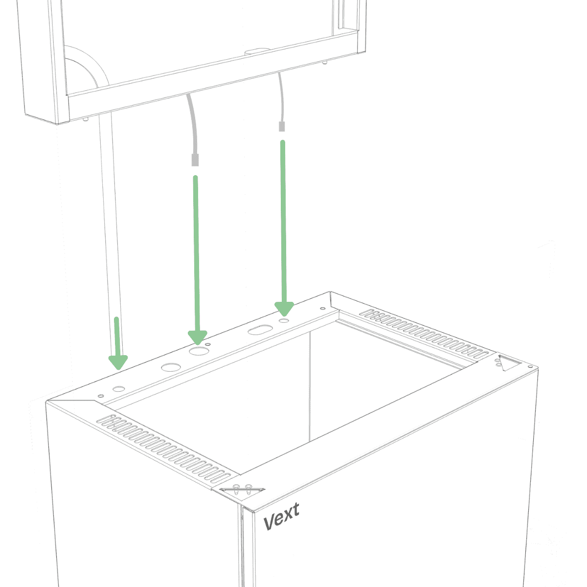
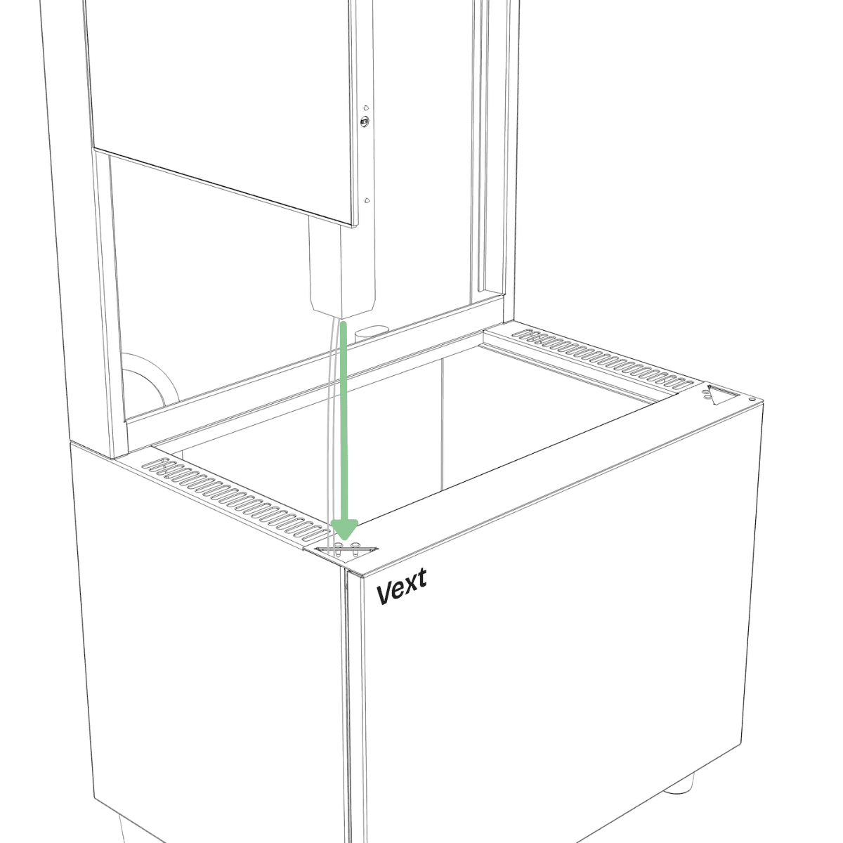
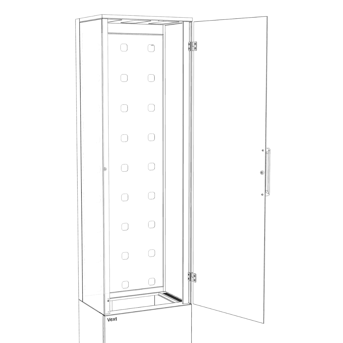
Step 5
Open Box A. Align the frame over the base, guiding the cables straight down through the corresponding holes.
NOTE:
Do not rest the frame on the cables coming out of the bottom, as this may deform the connectors and make installation more difficult.
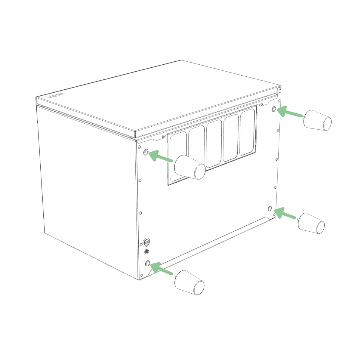
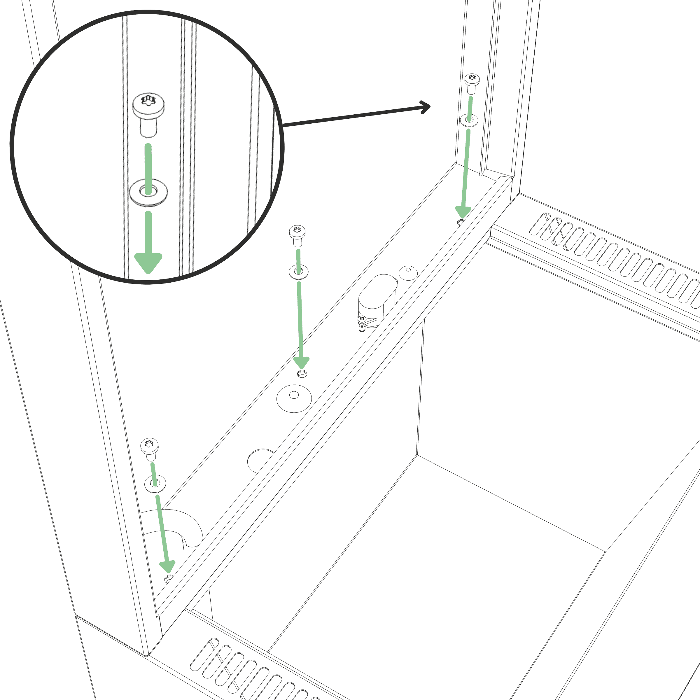
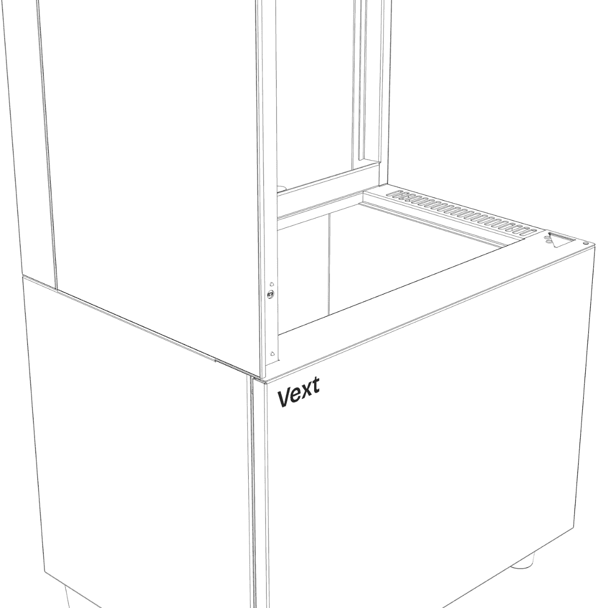
Step 6
Fasten the frame to the base using three M5 screws with sealing washers, with the rubber side of the washers facing down. Tighten until the washers are clearly compressed and the frame is firmly secured. (Tool: T25)
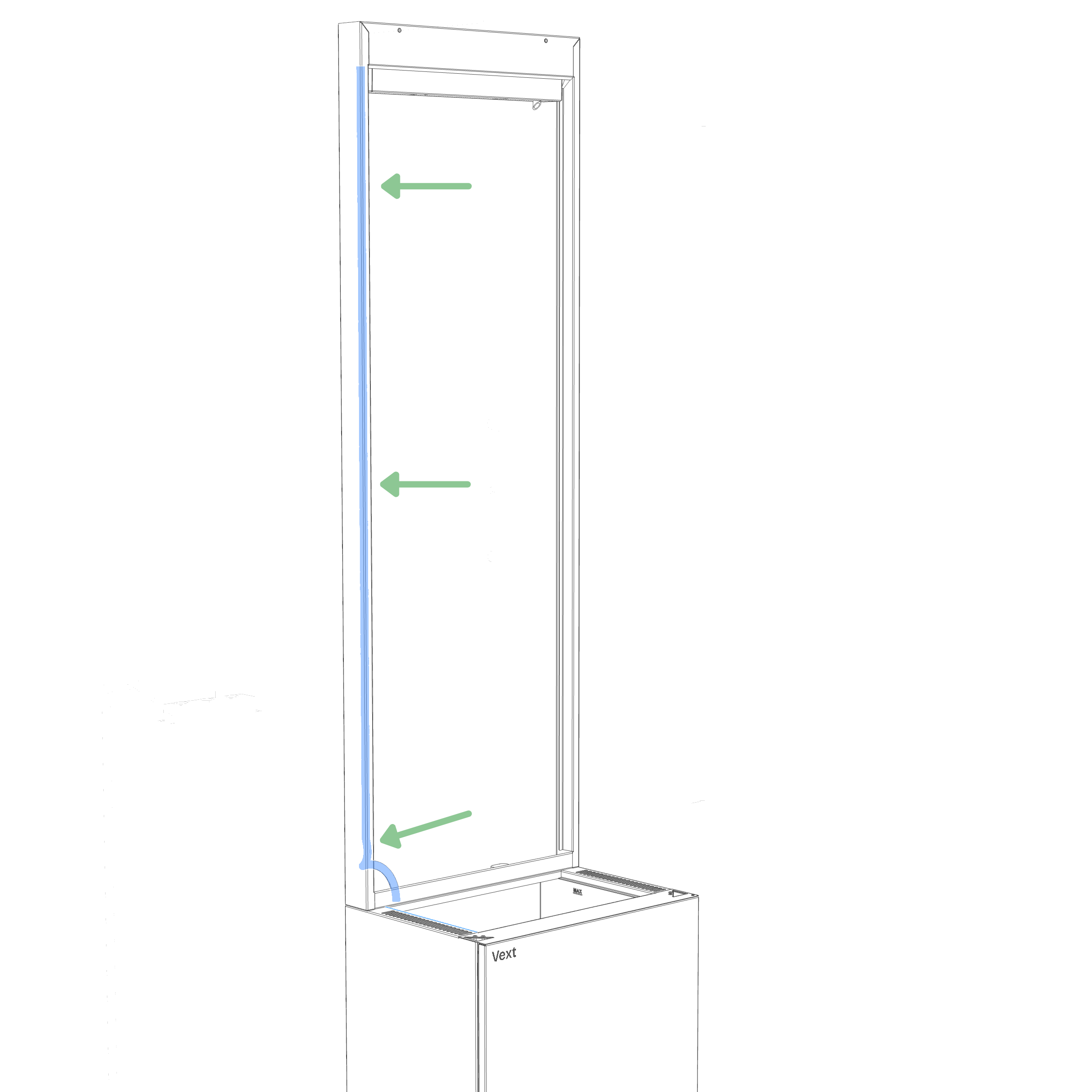
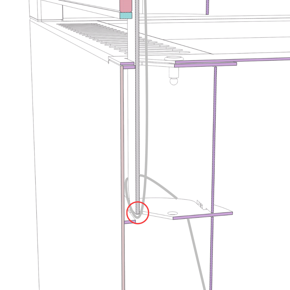
Cable and tube routing
Guide the cable and tube inside the frame into the groove in the front left corner, routing them from the bottom all the way to the top so they remain out of sight. This also helps prevent roots from attaching to them later.
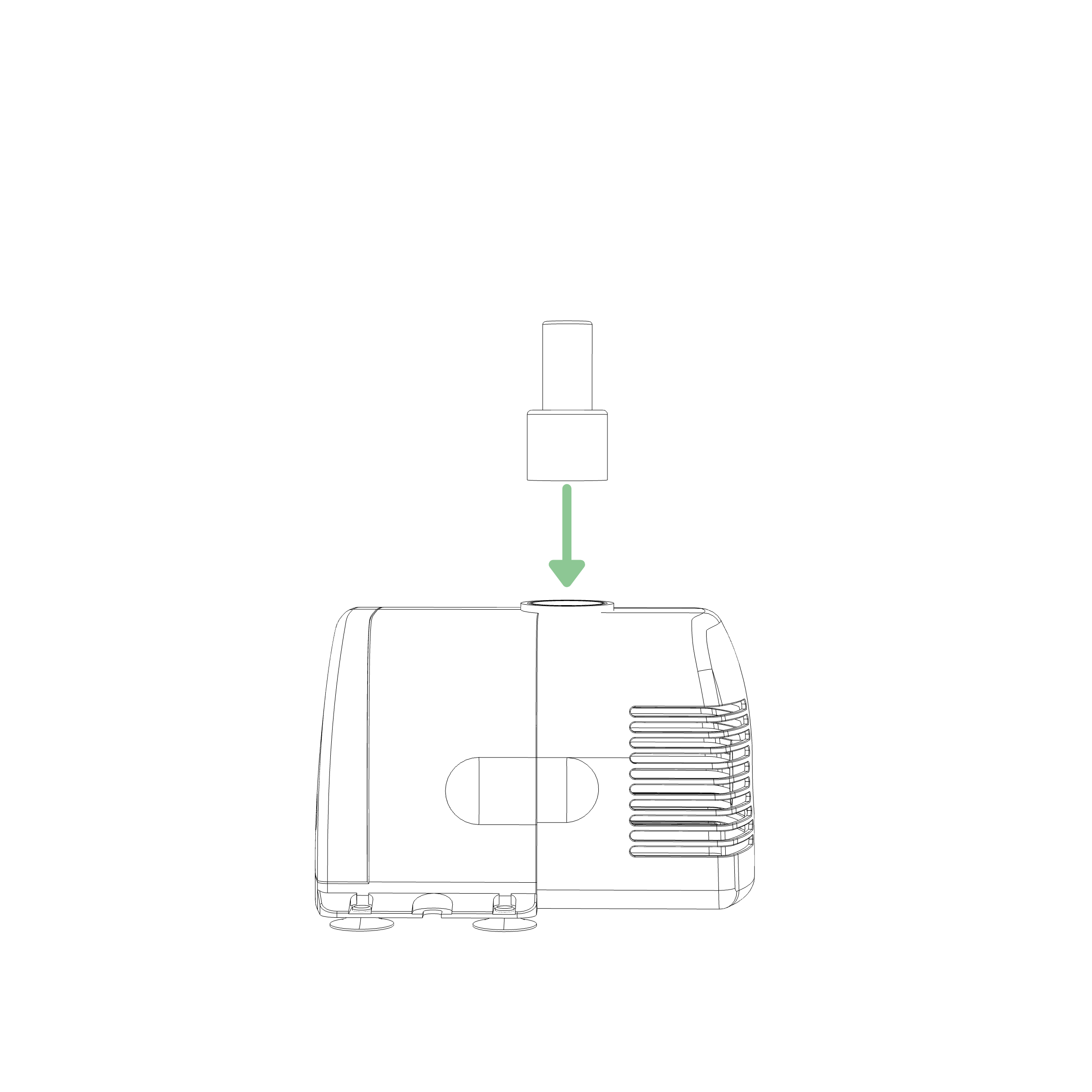
Step 7 Preparation
Take the plastic nozzle from the water pump box and push it into the water pump, wider end first, until fully seated.
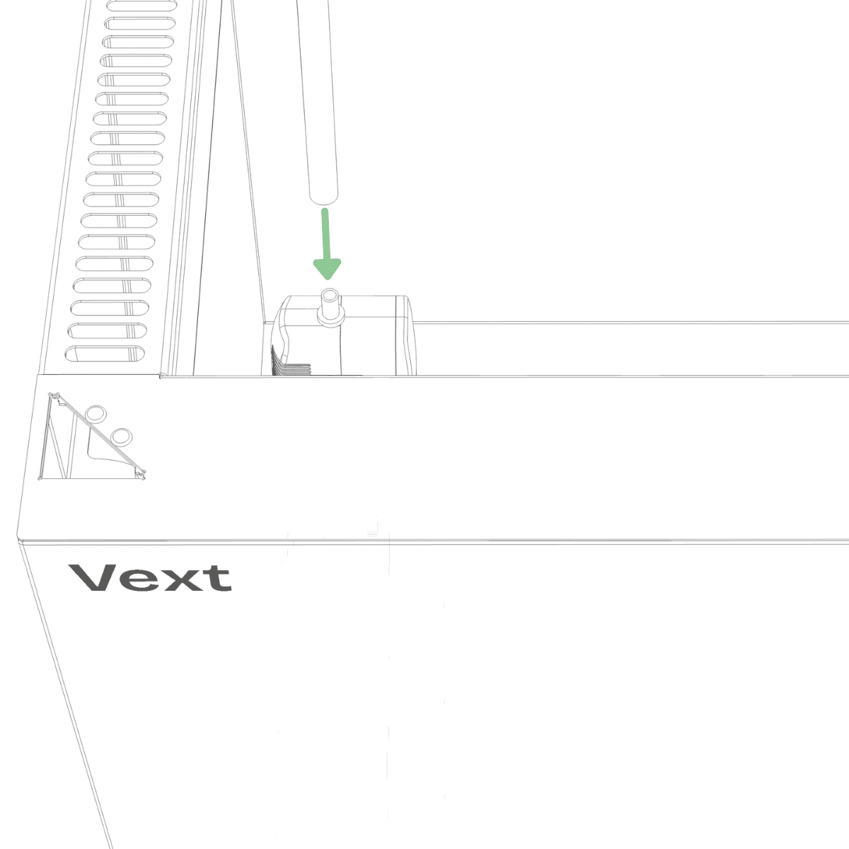
Step 7
Place the water pump in the back left corner of the water tank and attach the pump hose. If needed, gently pull the hose downward so the water pump rests fully at the bottom of the tank.
Step 8
Inside the water tank, locate the matching connectors for:
8.1. the water pump (small connector pair, left),
8.2. the fogger (large connector pair, left), and
8.3. the water level sensor (small connector pair, right).
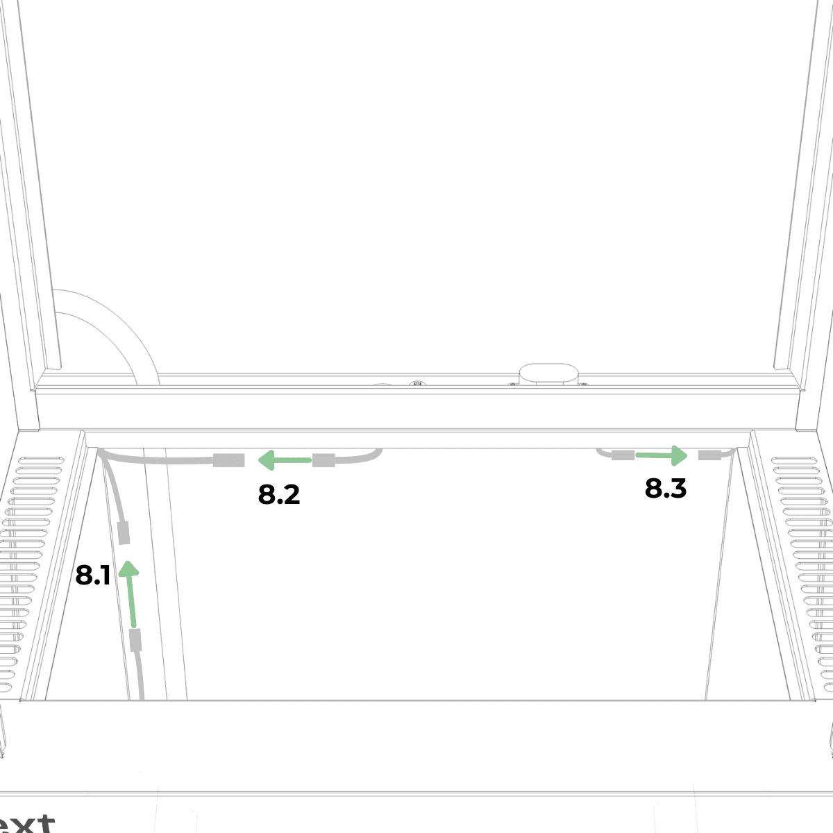
Step 9
Connect all three connector pairs by aligning the arrows, pushing them firmly until fully seated, then tighten the threaded collars until hand-tight.
Step 10 Preparation
Identify the left-glass module and verify its orientation before proceeding to the next step. The light bar extends further beyond the glass at the bottom than at the top.
Step 10
Position the left-glass module so that the bottom of the light bar is near the left triangular opening on the base.
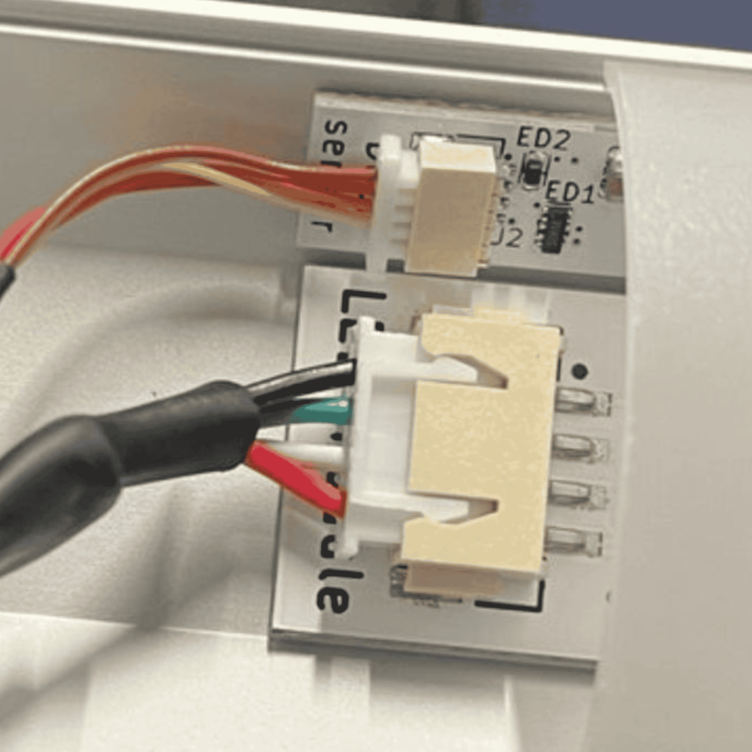
Step 11
Connect the small connector from the base to the small connector on the light bar, and the large connector from the base to the large connector on the light bar. Push each connector until fully seated.
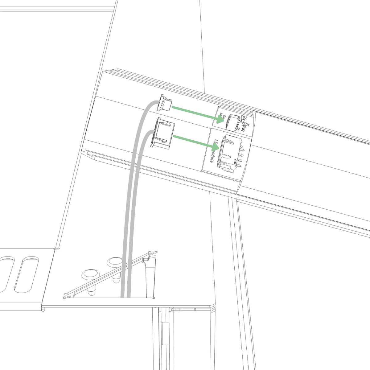
Step 11 Confirmation
The connectors are fully seated when they cannot be pushed in any further and match the picture below.
Step 12
Insert the light bar into the triangular opening in the base, keeping it perfectly vertical as you guide it through the second hole until it is flush with the top of the base.
NOTE:
Do not apply downward force when guiding the light bar into the second hole. If the light bar does not slide fully into place, cables may be trapped between the light pillar and the edge of the second hole. Remove the light bar and reinsert it carefully, ensuring that no cables are obstructing the hole.
Picture of what can happen inside the base unit
Step 13
The light bar is correctly inserted when the glass panel is fully in contact with the top of the base, with no visible gap.
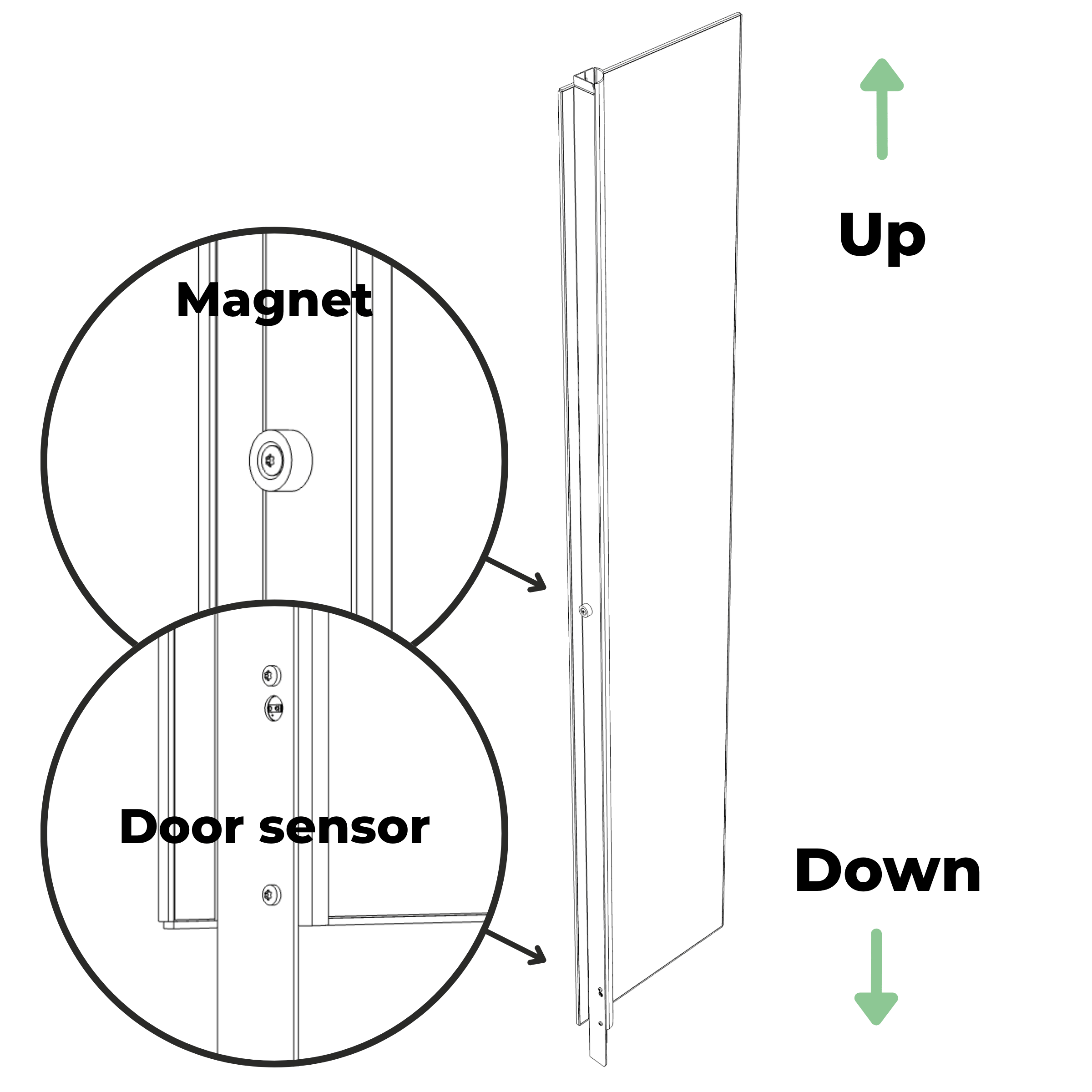
Step 14 Preparation
Identify the right-glass module and verify its orientation before proceeding to the next step. The light bar extends further beyond the glass at the bottom than at the top.
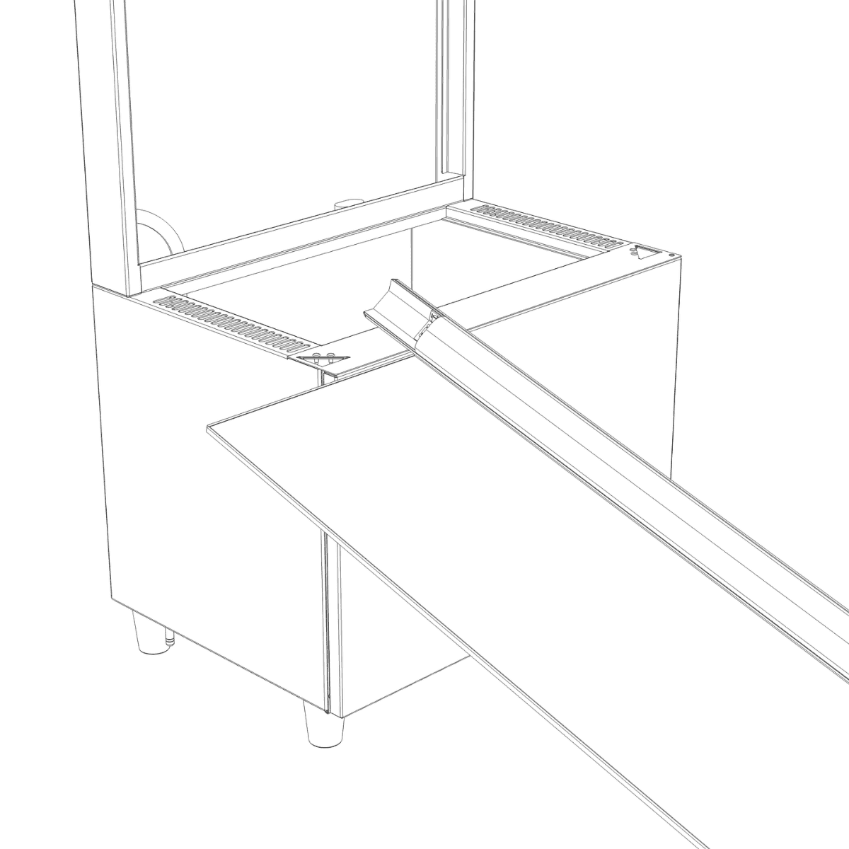
Step 14
Position the right-glass module so that the bottom of the light bar is near the right triangular opening on the base.
Step 15
Connect the small connector from the base to the small connector exiting the bottom of the light bar, and the large connector from the base to the large connector on the light bar. Push each connector until fully seated. Then push the cable of the small connector as far as possible into the triangular hole.
Step 16
Insert the light bar into the triangular opening in the base, keeping it perfectly vertical as you guide it through the second hole until it is flush with the top of the base.
NOTE:
Do not apply downward force when guiding the light bar into the second hole. If the light bar does not slide fully into place, cables may be trapped between the light bar and the edge of the second hole. Remove the light bar and reinsert it carefully, ensuring that no cables are obstructing the hole.
Step 17
The light bar is correctly inserted when the glass panel is fully in contact with the top of the base, with no visible gap.
Step 18 Preparation
Partially fasten two M5 screws into the front of the frame.
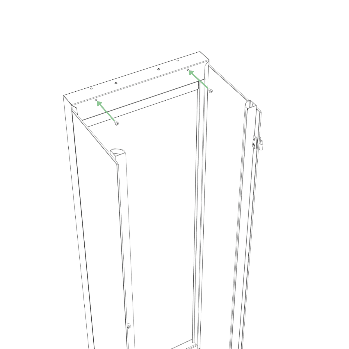
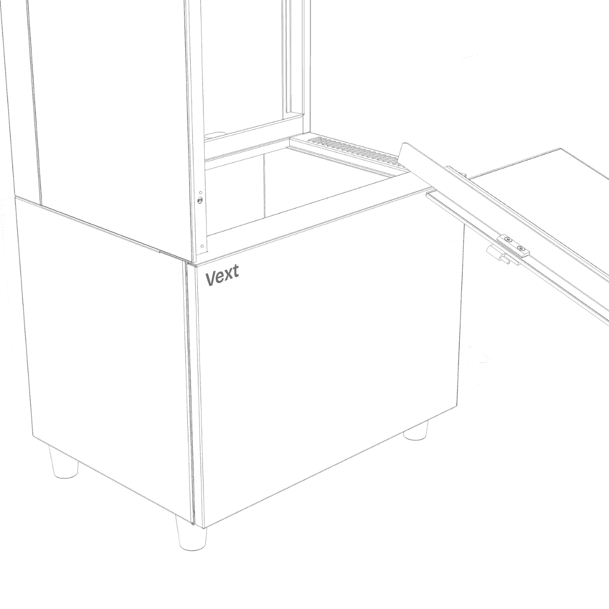
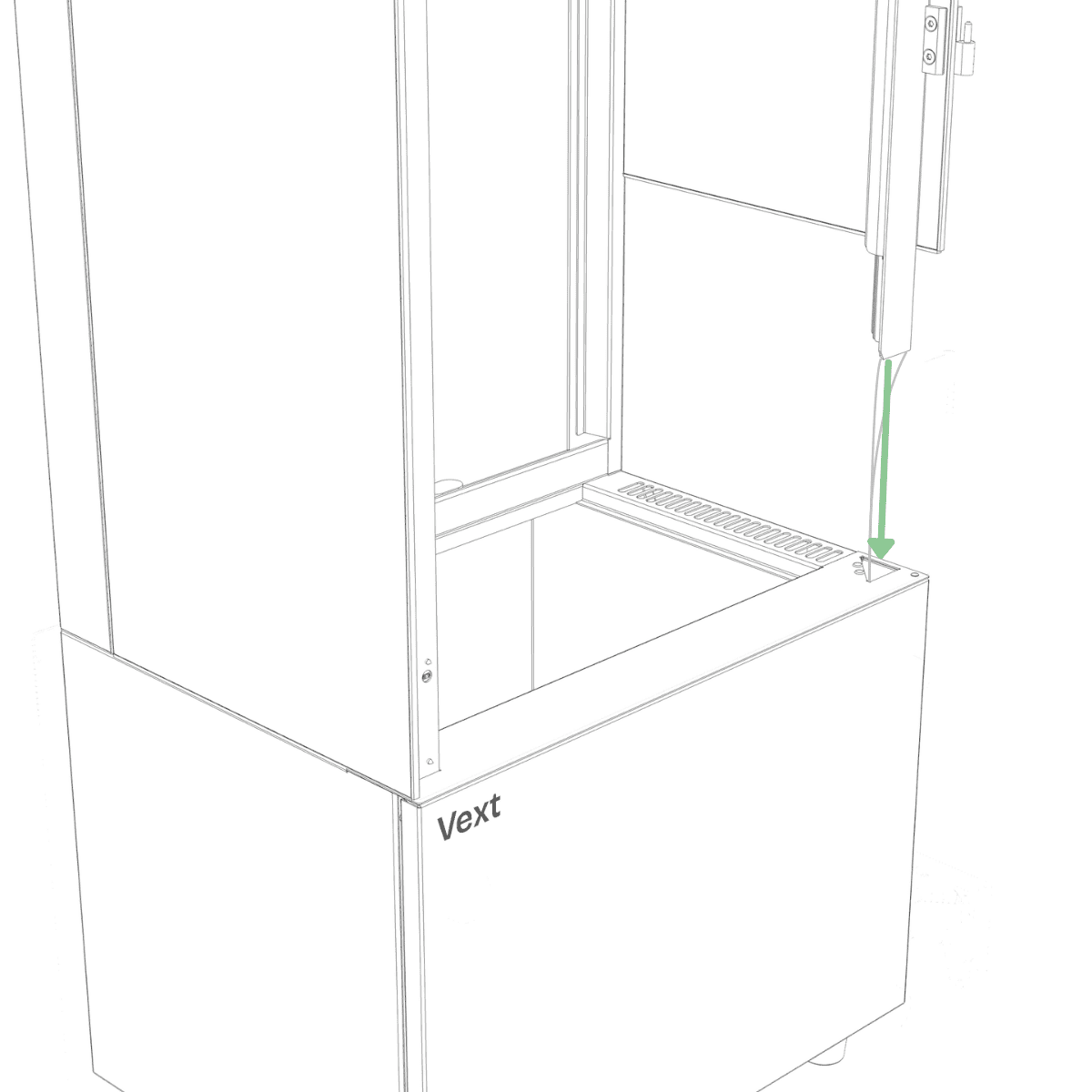
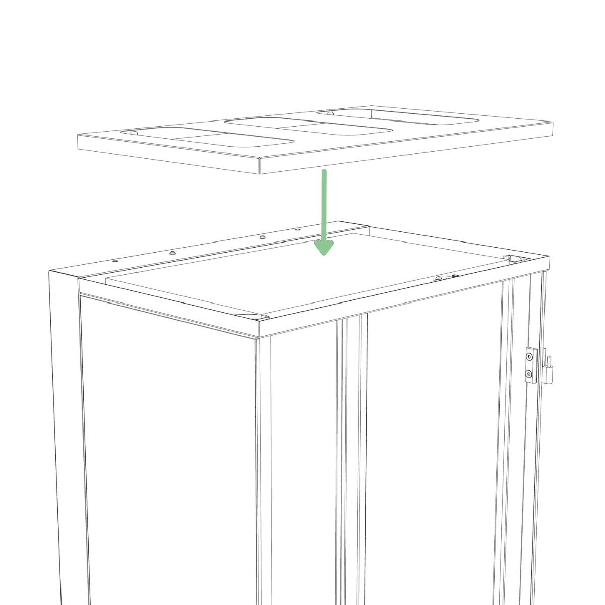
Step 18
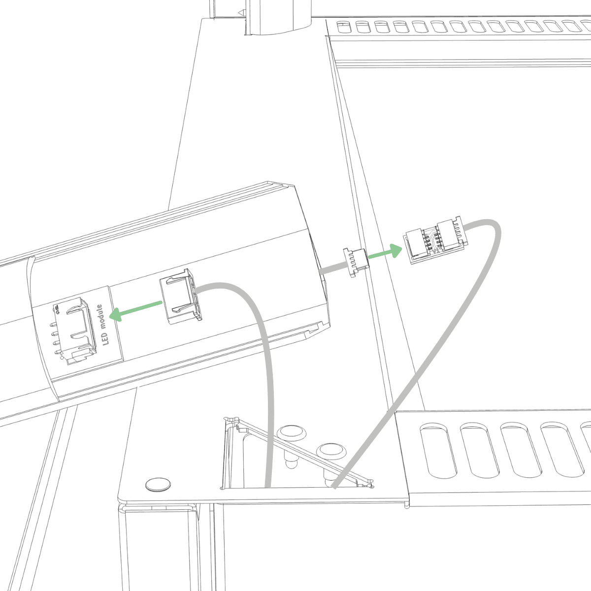
Remove the top panel from Box B. Route the cable coming from the top of the right light bar through the hole in the right front corner of the top panel.
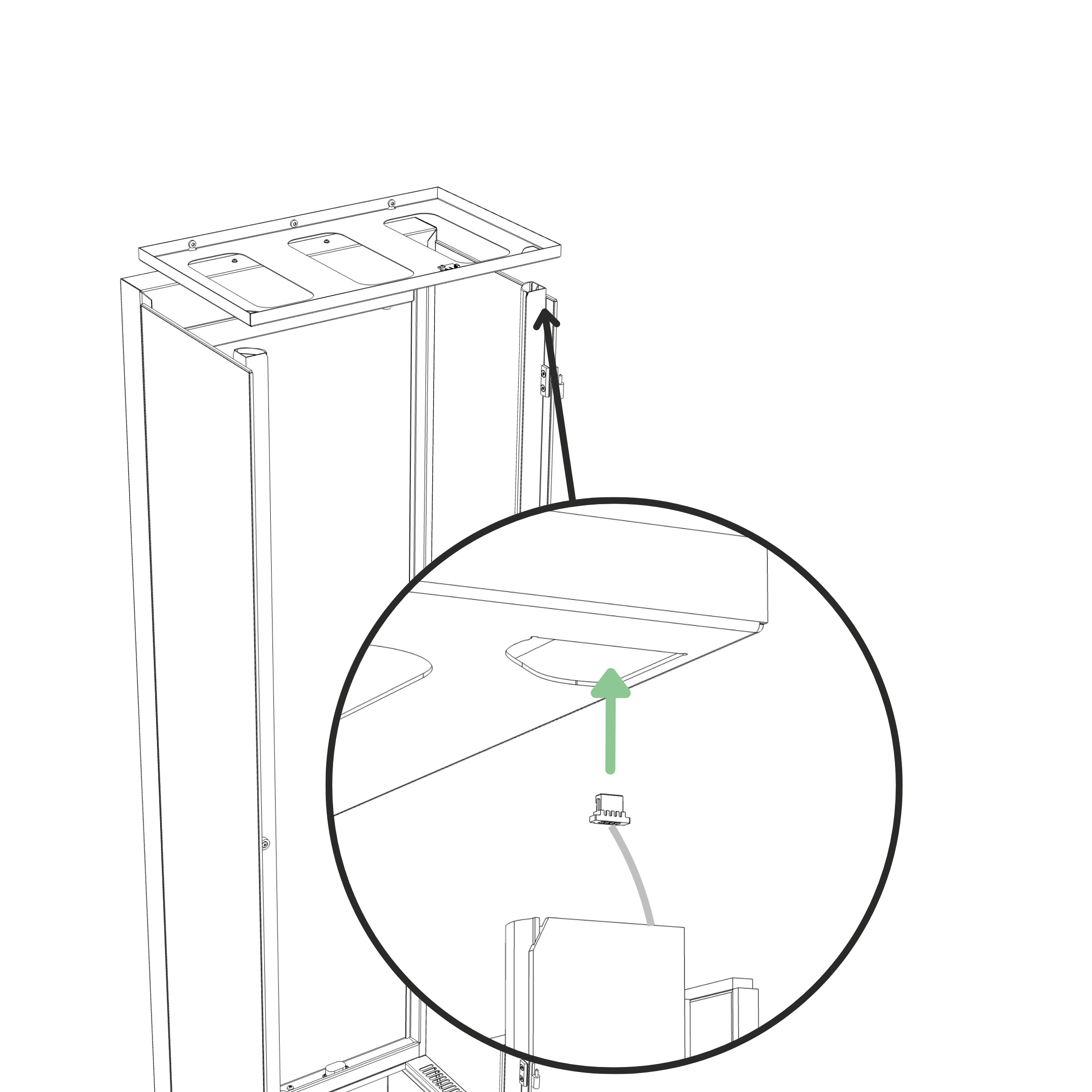
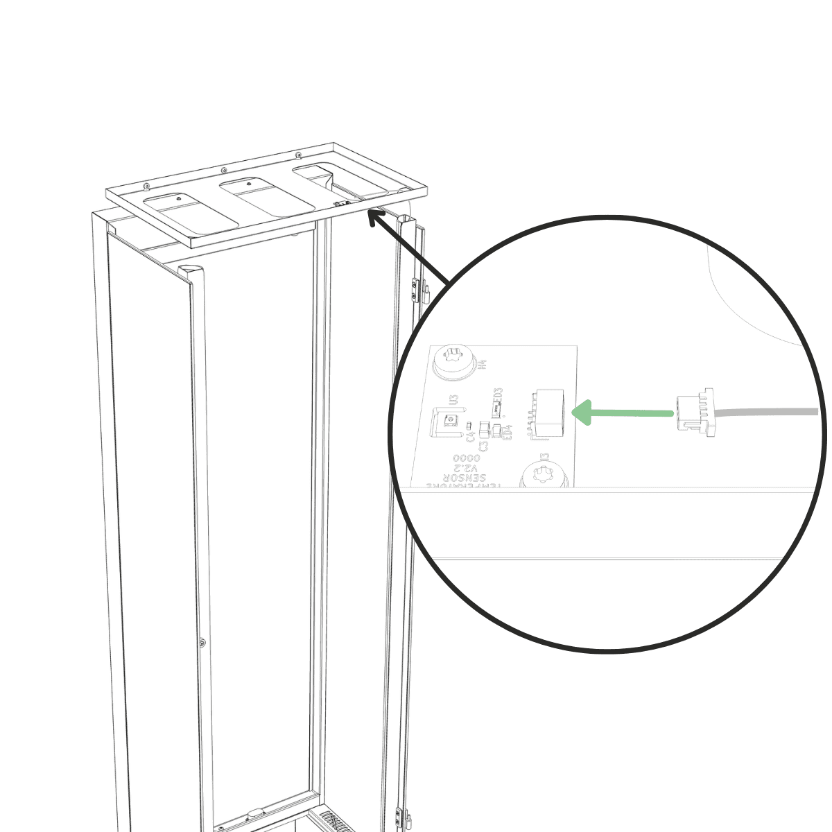
Step 19
Connect the small connector to the sensor on the top panel. Push until fully seated.
Step 20
Slot the top panel onto the two M5 screws on the frame.
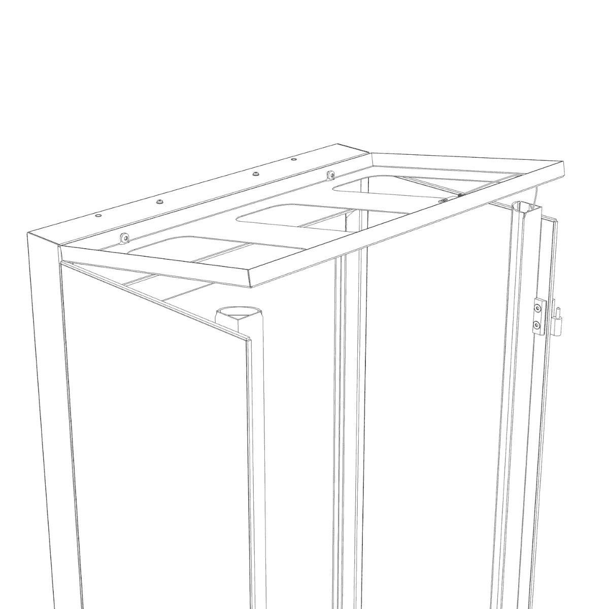
Step 21
Press the top of the plastic LED cover inward toward the aluminium profile while lowering the top panel so the triangular hole slides over the light bar. Repeat for the other light bar.
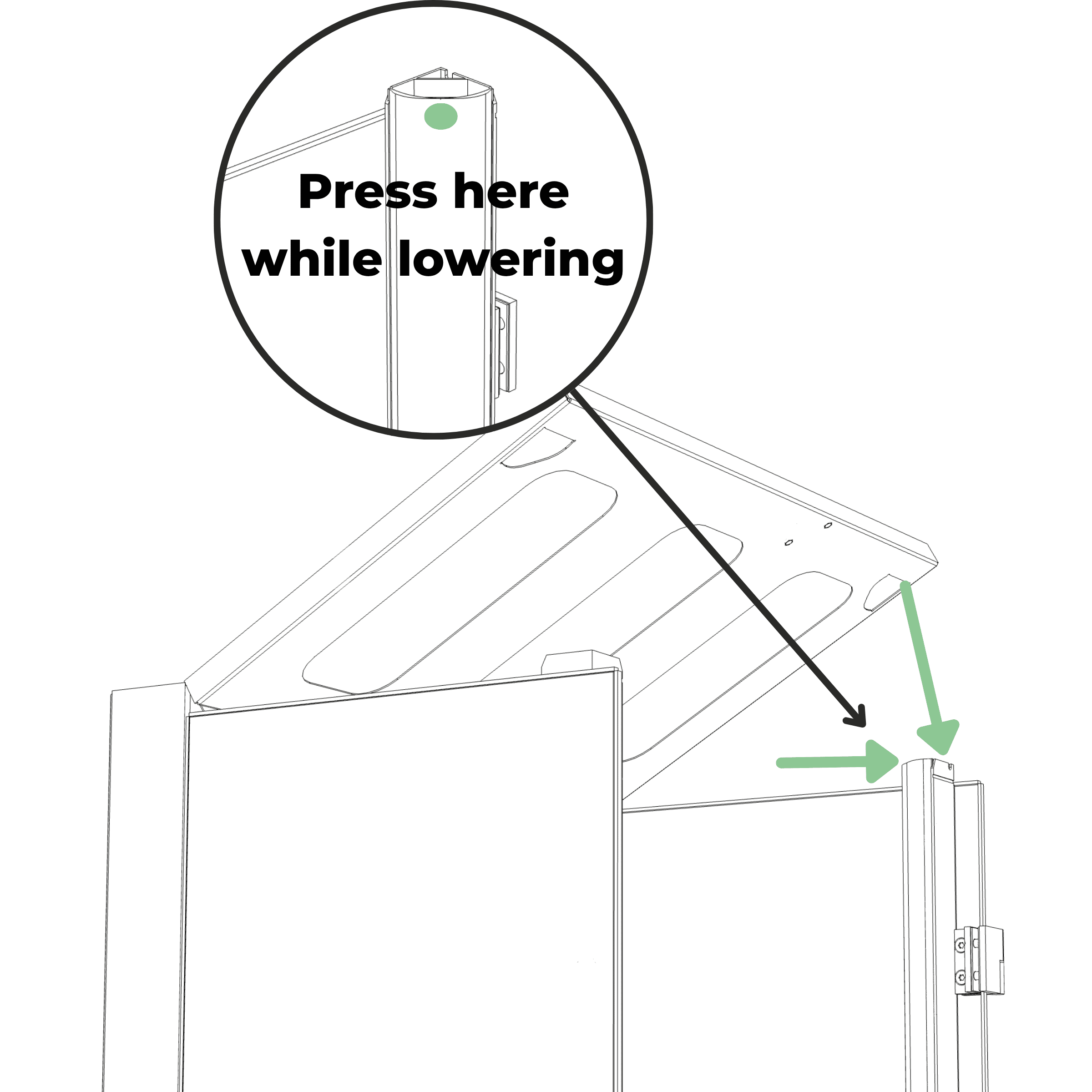
Step 22
Ensure the glass panels are aligned flush along the entire back edge so the sides of the cabinet are completely flat, then while holding down the back of the top panel at the sides, tighten the two M5 screws. (Tool: T25)
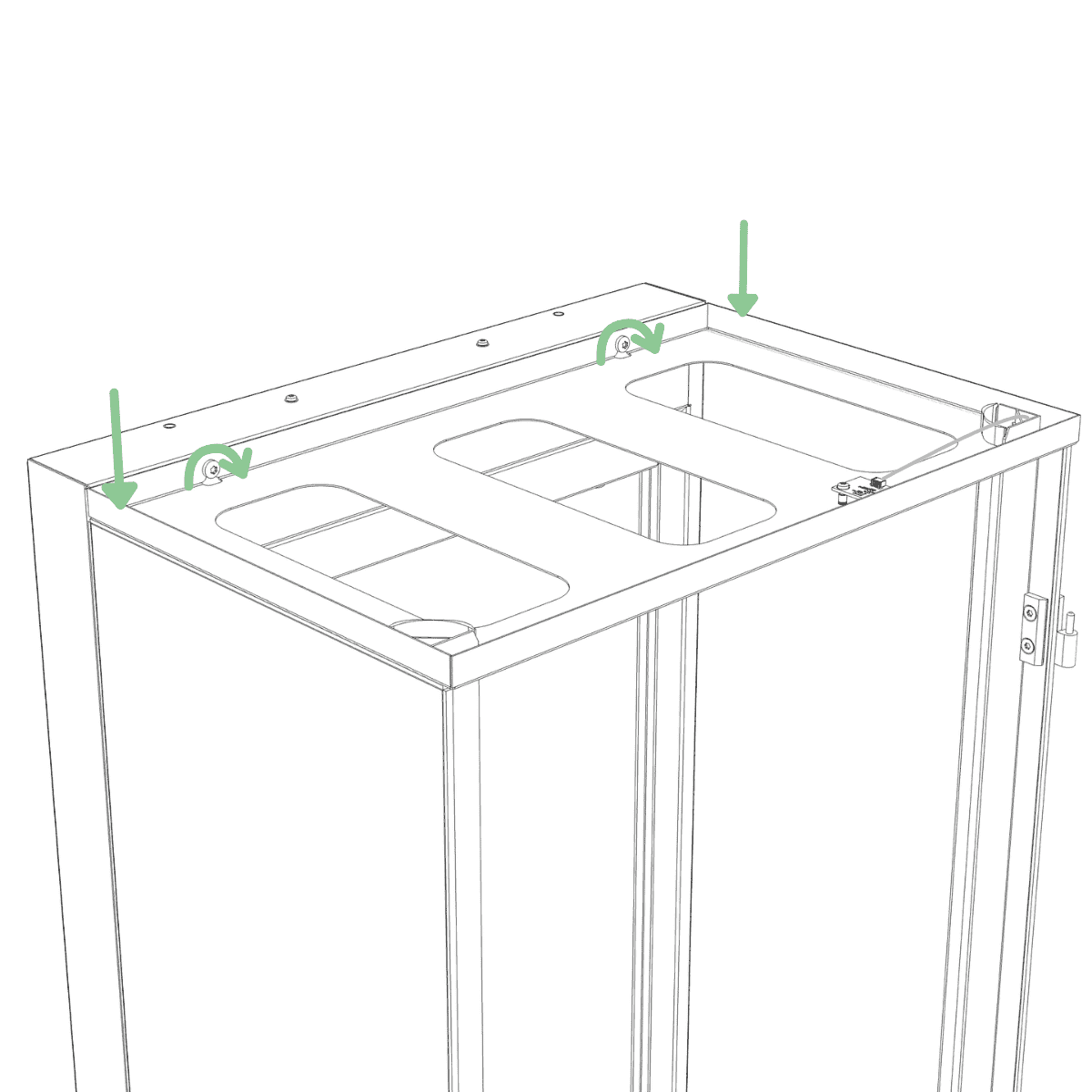
Step 23
Insert the top filter into the top panel.
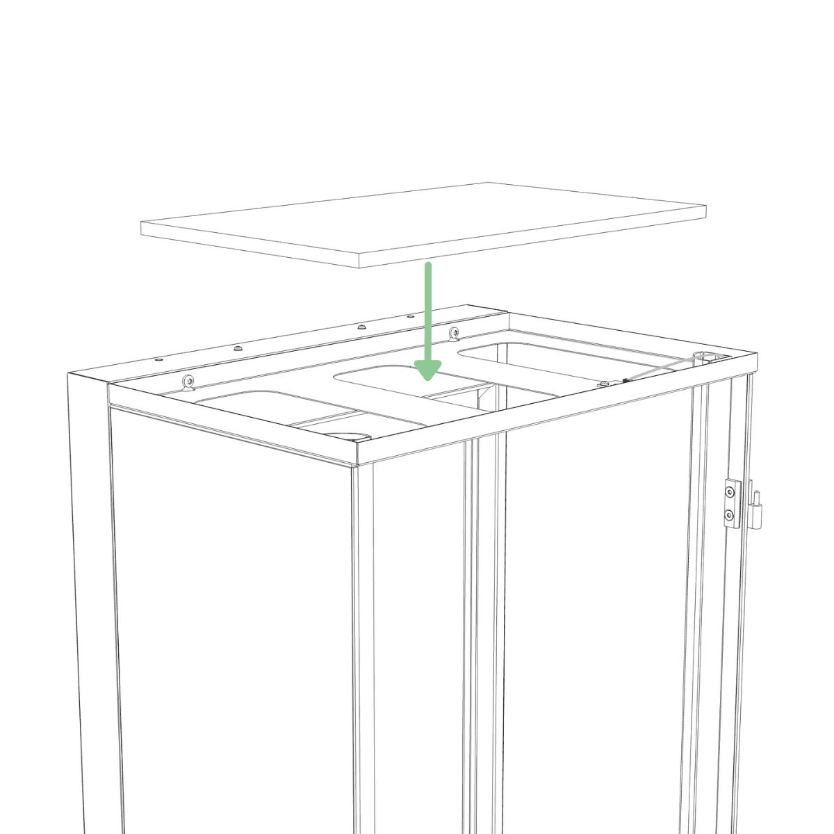
Step 24
Place the filter cover into the top panel.
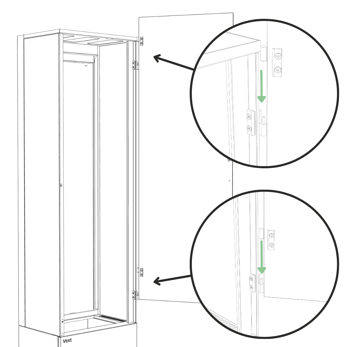
Step 25
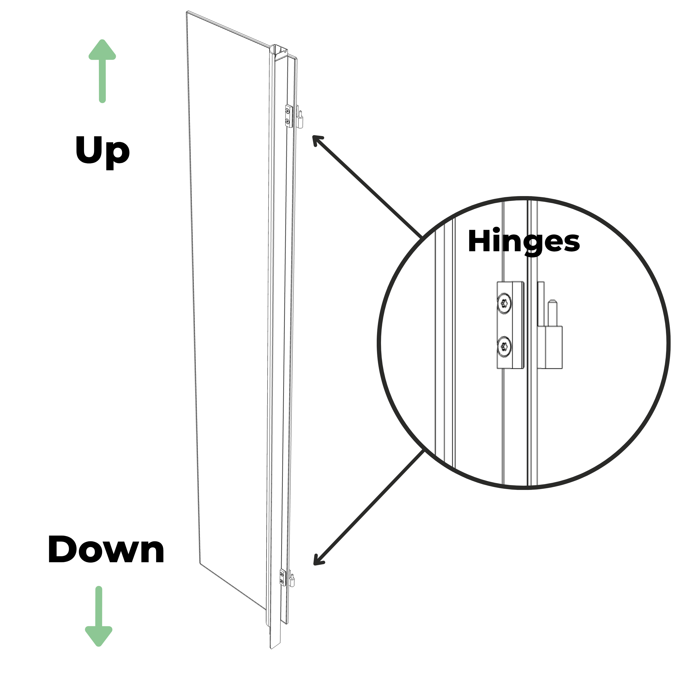
Lift the glass door, supporting it from the bottom with one hand, and align the hinge pins with the hinge holes, then lower the door into place.
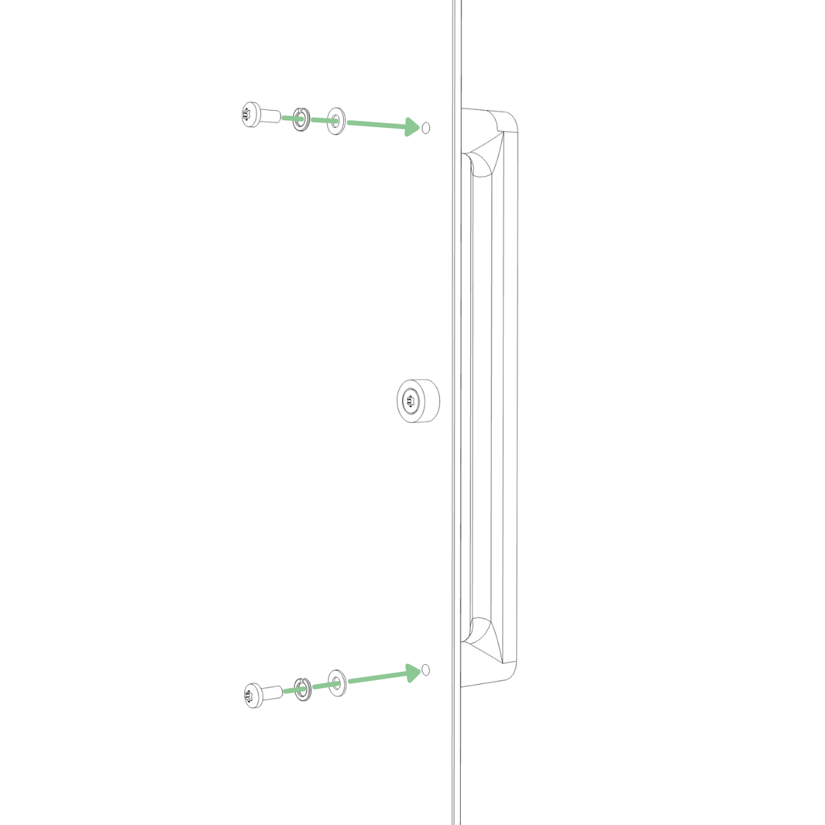
Step 26
Attach the door handle to the glass door using two M4 screws, each with a spring washer under the screw head and a washer against the glass. Tighten securely. (Tool: T20)
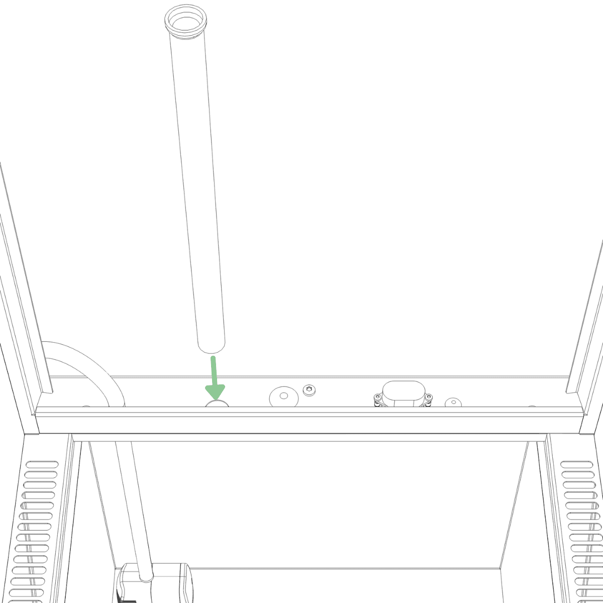
Step 27
Locate the large hole in the bottom of the frame. From above the water tank, insert the drain tube through the hole, then gently pull it downward until it can no longer be pulled further.
Step 28
Lift the plant wall by the top corner holes and place the lower corners into the frame first, then tilt it upright into position.
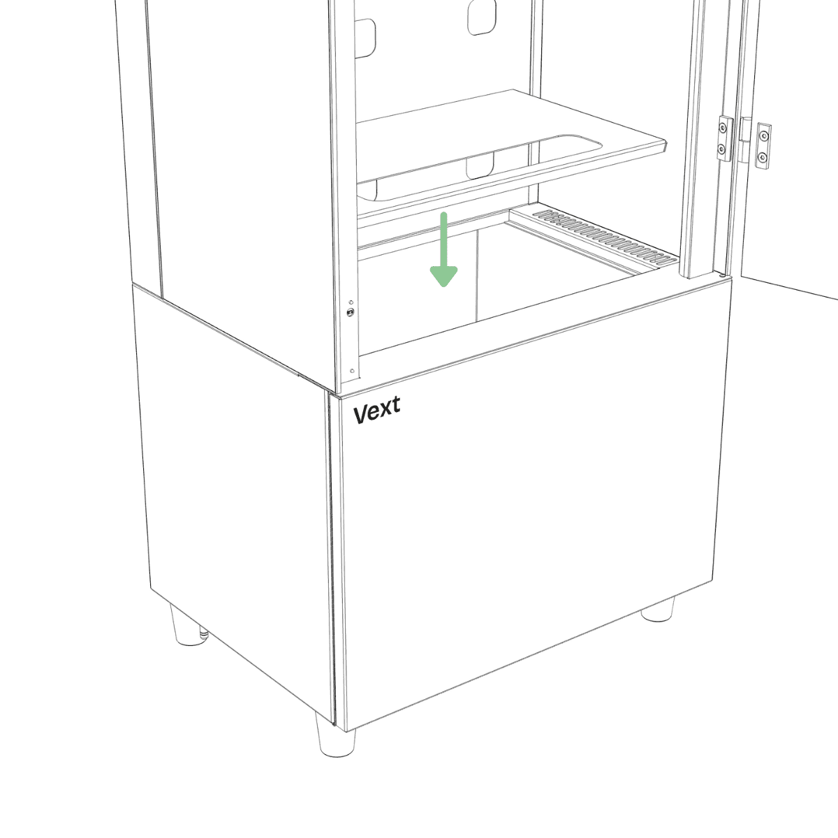
Step 29
Place the water tank lid on the water tank.
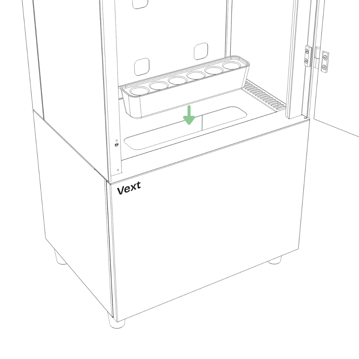
Step 30
Insert the plant starter into the hole on the lid.
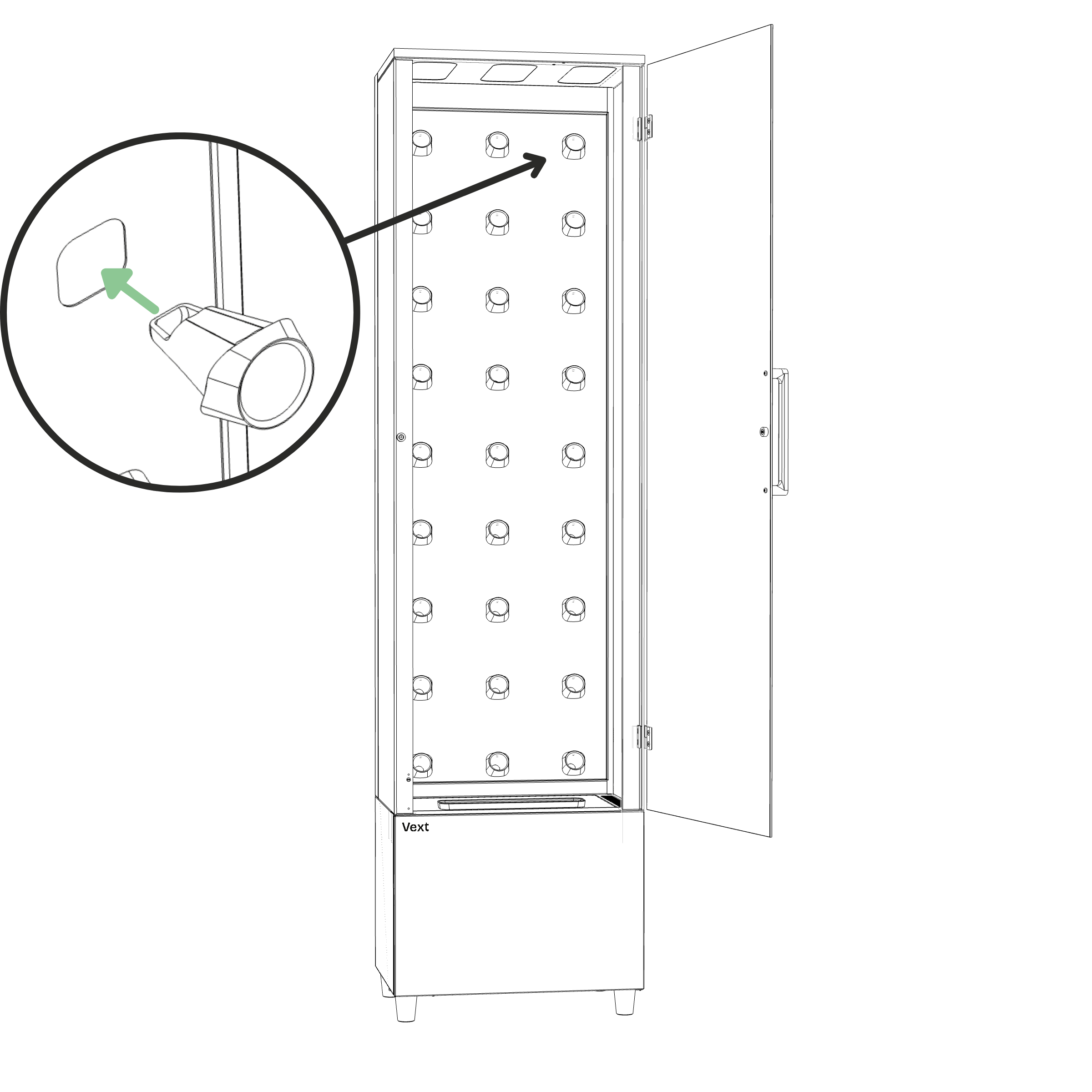
Step 31
Insert the pod holders into the holes of the plant wall. To insert a pod holder, press one side in first, then the other, until it snaps into place.
Assembly is complete when all components are installed, the cabinet is upright in its final location, and all connectors are securely seated.
Securing to wall (Recommended)
CAUTION – Risk of tipping
Secure the cabinet to a wall if children or pets are present, or in areas where earthquakes or seismic activity may occur.
Step 1
Ensure the cabinet is level and in its final position against a solid wall.
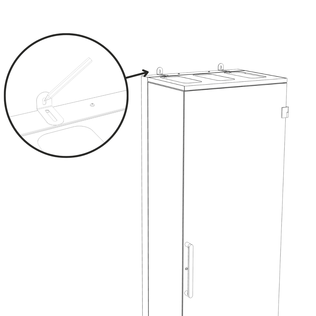
Step 2
Hold the brackets against the wall and align them with the holes at the top of the cabinet. Mark the drilling points with a pencil.
NOTICE – Bracket installation
Use plugs and screws appropriate for your wall type and the weight of the cabinet (Bracket slots are designed for screw shanks up to Ø 5 mm).
Do not fasten to plasterboard, hollow, or soft walls.
Step 3
If required for your wall type:
Drill holes at the marked points using a suitable drill bit for your wall material.
Insert suitable wall plugs into the drilled holes.
Step 4
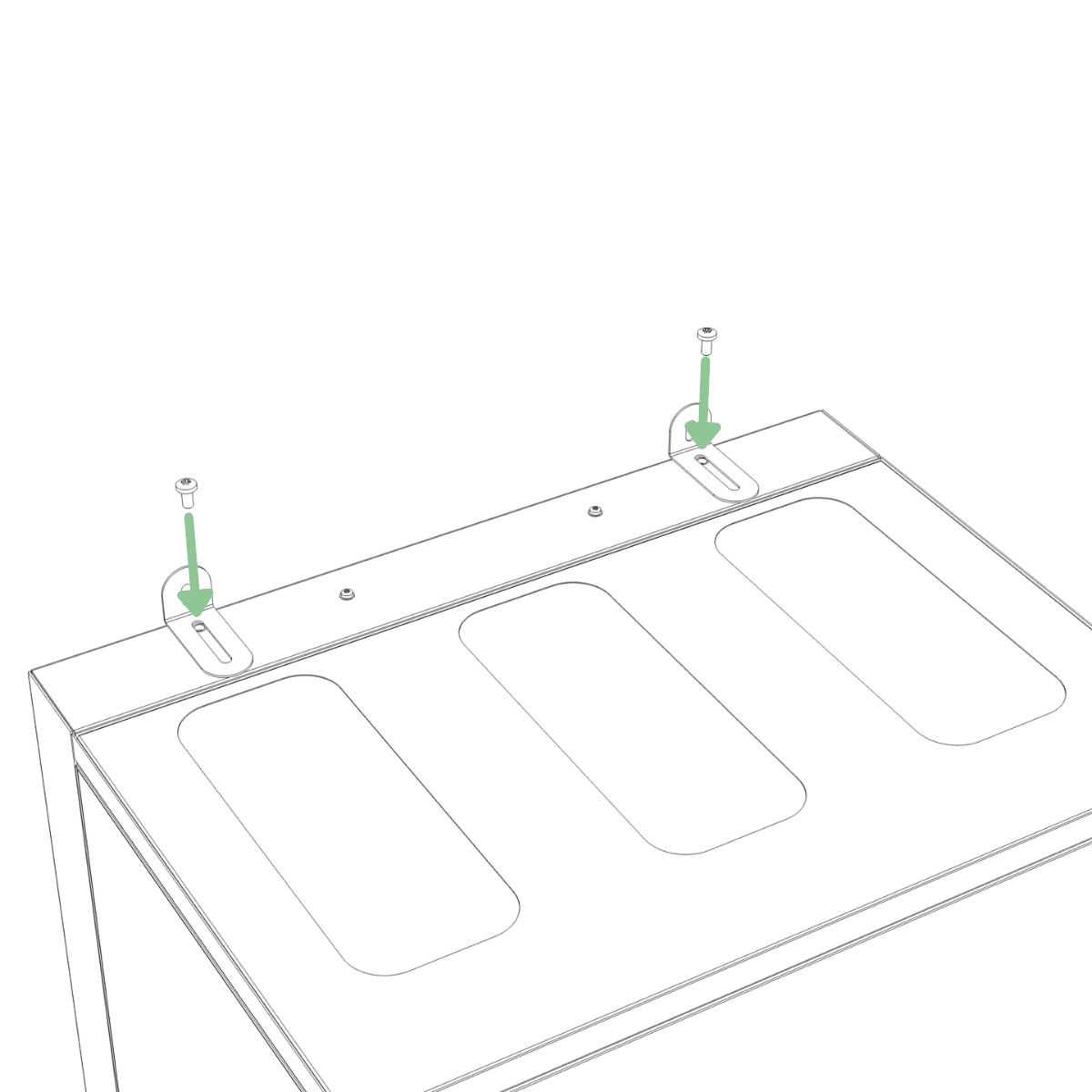
Fasten the brackets to the top of the frame using two M5 screws. (Tool: T25)
Step 5
Fasten the brackets to the wall using suitable screws.
Startup
WARNING – Before connecting power
Ensure all connectors are fully inserted and correctly connected as described in the assembly steps.
Step 1
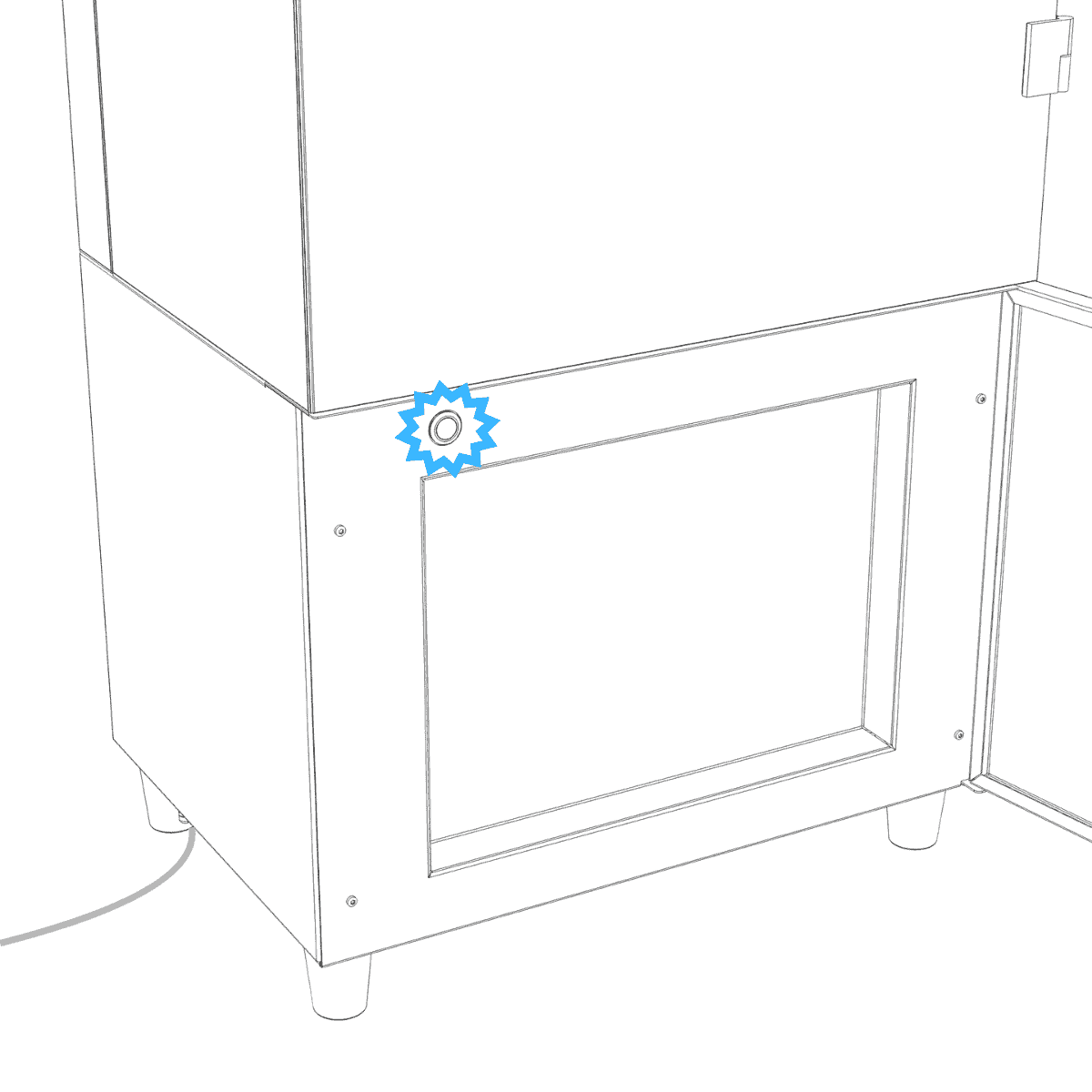
Insert the power cable into the power connector at the bottom left of the cabinet.
Step 2
Plug the other end into a grounded mains socket.
Step 3
After connecting power, wait approximately 30 seconds for the cabinet to start automatically. The cabinet has started once the lights turn on and the button starts blinking blue. No further action is required.
(If button light turned yellow follow the instructions below)
If button light turned yellow
When connecting power for the first time, the button light may turn yellow while the cabinet runs the pump and lights as part of its startup. Wait until the button light turns either green or red.
If the button light turns green, unplug the power cable and plug it back in. The cabinet then automatically enters Bluetooth pairing mode, indicated by a blinking blue light at the bottom.
If the button light turns red, press and hold the button until the light turns blue. This may take approximately 20 seconds.
Connecting and first tasks
Once assembly is complete, leave this assembly guide and continue setup in the app. Follow the on-screen steps to pair your phone and connect your cabinet to Wi-Fi.
Once the cabinet is connected to Wi-Fi, your first tasks will appear on the home page. Complete these and your cabinet is ready to start growing.
Feedback
If you have any thoughts on the assembly process, we would love to hear them. Reach us at support@vext.fi.